Select the type of FF going to use. If load 0 then it will spit out the output of the preceding flip flop.

Binary Counter With Parallel Load Youtube
Before proceeding to any step it is imperative to create a New Project Wizard in the software.

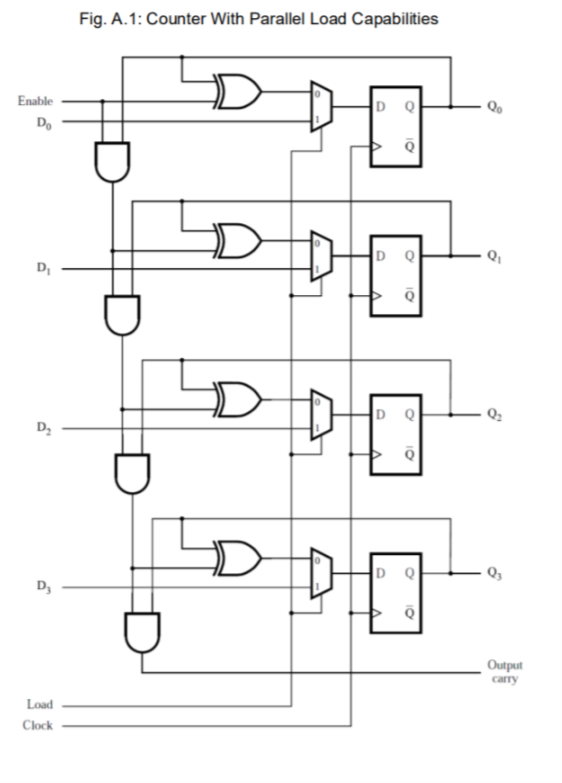
. 514 Design a four-bit synchronous counter with parallel load. We can find out by considering a number of bits mentioned in the question. The first attempt of designing a 4-Bit binary counter with parallel load is the proposed circuit.
Use T flip-flops instead of the D flip-flops used in Section 593 516 Repeat Problem 515 using D flip-flops. Here we will learn to write a verilog HDL to design a 4 bit counter module counterclkresetup_downloaddatacount. If UpDown 0 then the circuit should behave as an up-counter.
Our proposed circuit has minimum value of the quantum cost. In the above image the basic Synchronous counter design is shown which is Synchronous up counter. Please Like Share and subscribe to my channel.
3- Design a four-bit synchronous counter with parallel load. Same clock pulse is given to each flip-flop. It should include a control input called UpDown.
Fundamentals of Digital Logic. -- overriding load sel 0. A 4-bit Synchronous up counter start to count from 0 0000 in binary and increment or count upwards to 15 1111 in binary and then start new counting cycle by getting reset.
Design a four-bit synchronous counter with parallel load. Always block will be executed at each and every positive edge of the clock alwaysposedge clk begin ifreset Set Counter. Sel 1.
The flip-flops are clocked at the same time by a common clock pulse. Then with clock pulse counts like 0001. Synchronous Parallel Counters Synchronous parallel counters.
We can design these counters using the sequential logic design process covered in Lecture 12. 3- Design a four-bit synchronous counter with parallel load. Evaluation of the proposed circuit can be realized easily with the results in Table 2.
So lets assume that we wanna load the data which is 0010. 2-bit synchronous binary counter using T flip-flops or JK flip-flops with identical JK inputs. Use T flip-flops instead of the D flip-flops used in Section 593.
So in this we required to make 4 bit counter so the number of flip flops required is 4 2 n where n is a number of bits. See figure attached for my attempt. Electrical Engineering questions and answers.
Design of a nanometric reversible 4-bit binary counter with parallel load In recent years reversible. After that we need to construct a state table with excitation table. Counter is basically a register that goes through a predetermined order of conditions.
Construct the state table containing current state and next state of the counter and the excitation table of FFs used. Design A Four Bit Synchronous Counter With Parallel Load Design a four bit synchronous counter with parallel load Then again it doesnt imply that If youre able tot produce your very own nail art youll be able to in no way have Those people adorable nails. Its operating frequency is much higher than the same range Asynchronous.
It should include a control input called Up Down. I hooked up a standard counter using T flip flops and AND gates and then for the parallel load I created a load input that runs into 4 2-1 MUXs. The load must be at logic 0.
If UpDown 0 then the circuit should behave as an up-counter. Implementation The Four-Bit Synchronous Up Counter circuit is constructed in Quartus 2 software package with web-version of 121 running on a 64-bit configuration. Like all sequential circuits a finite-state machine determines its outputs and its next state from its current inputs and current state.
It has lowest number of reversible gates constant inputs and garbage outputs. 514 Design a four-bit synchronous counter with parallel load. The planned circuit is the first attempt of designing a 4-Bit binary counter with parallel load.
40 Design of Synchronous Counters This section begins our study of designing an important class of clocked sequential logic circuits-synchronous finite-state machines. The proposed reversible circuit is the first attempt of design a 4-Bit binary counter with parallel load. Use T flip-flops instead of the D flip-flops used in Section 593.
Define input and ouput ports input clkresetloadup_down. To design a synchronous up counter first we need to know what number of flip flops are required. At first we have twoo main states.
Use T flip-flops instead of the D flip-flops. 3- Design a four-bit synchronous counter with parallel load. It is an up counter and starts from 0000.
Output reg 30 count. Where load takes precedence over counting. Download scientific diagram 4-Bit Binary Counter with Parallel Load.
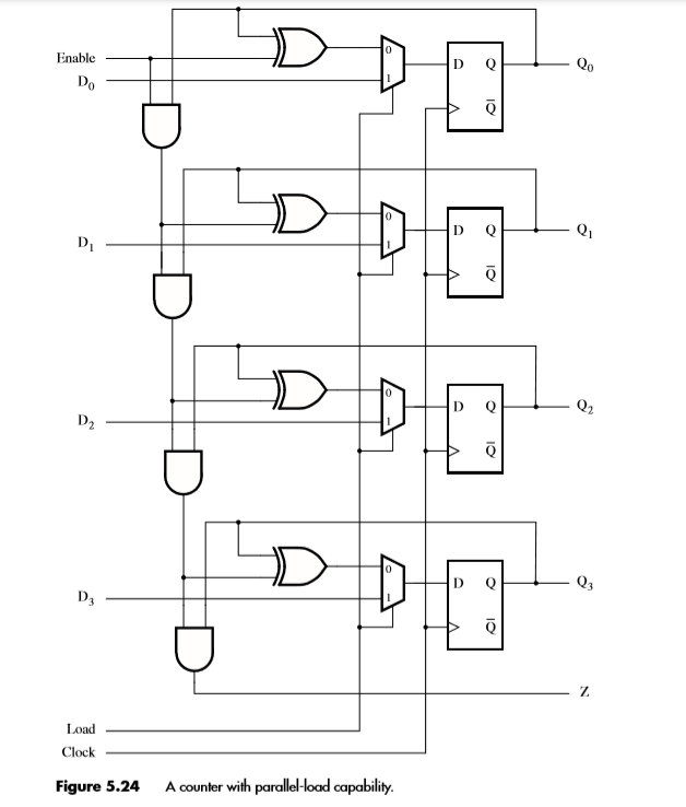
Note that equations for 10 and 11 values of sel are combined on the following codes MUX0 you can use a 4 input. Solutions for Chapter 7 Problem 15P. Identify the numbers of flip-flops FFs inputs and outputs required for the count sequence.
Use T flip-flops instead of the D flip-flops 4- Design a three-bit updown counter using T flip-flops. If UpDown 1 then the circuit should behave as a down-counter. Design a fourbit binary synchronous counter with D flipflops Complete design steps-----.
So with every clock pulse the counter counts one step up. It should include a control input called UpDown. It should include a control input called UpDown.
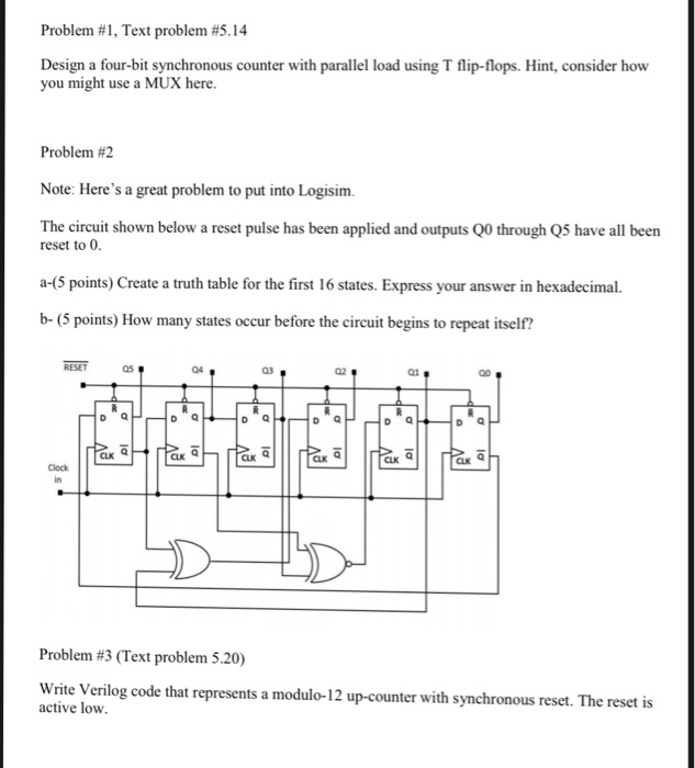
515 Design a three-bit updown counter using T flip-flops. This problem has been solved. Design a four-bit synchronous counter with parallel load using T flip-flops.
Synchronous Counter design procedure for a given counting sequence. 4-Bit Synchronous Up Counter 5 an LED. With VHDL Design with CD-ROM 2nd Edition Edit edition.
1- to Enable the. The reversible gates in the counter are connected in such a way as to produce the prescribed sequence of binary states. The select lines for that would be.
The sel inputs are used to all four multiplexer. 514 Design a four-bit synchronous counter with parallel load. Because this is a synchronous counter then we will assume that Clk is at logic high 1 all the time.
If UpDown 0 then the circuit should. Synchronous 4-Bit Up Counter The proposed synchronous 4-bit up counter has 3 AND gates 4 XOR gates and 4 master-slave D flip-flops. 515 Design a three-bit updown counter using T flip-flops.
Use T flip-flops instead of the D. If UpDown 1. 515 Design a three-bit updown counter using T flip- flops.
2- we can enable the load regardless of the value of the count.
Solved Fig A 1 Counter With Parallel Load Capabilities Chegg Com

4 Bit Binary Counter With Parallel Load Download Scientific Diagram
Solved Using A 4 Bit Synchronous Counter With Parallel Load Chegg Com

4 Bit Binary Counter With Parallel Load Download Scientific Diagram

Synchronous Counter With Parallel Load Youtube

Solved 5 14 Design A Four Bit Synchronous Counter With Parallel Load Use 1 Answer Transtutors
Solved Design A Four Bit Synchronous Counter With Parallel Chegg Com
Solved Problem 1 Text Problem 5 14 Design A Four Bit Chegg Com
0 komentar
Posting Komentar